Improving Manufacturability with Quality Product Design
A snap fit design can be your best friend or your worst enemy. We use them every day. You might think about the closure on the back of your TV remote or computer mouse, but they show up in applications of all industries. Snap fits offer faster and more economical assembly than mechanical options such as fasteners, adhesives, and welding.
A properly executed snap fit design should:
- Provide feedback like a tactile lock and audible click
- Be simple but not too easy to engage and disengage
- Be intuitive to use and economical to manufacture
Designing for snap fits can be a tricky process. If incorrectly done, it will lead to mismatched or unusable part assemblies.
Most collective wisdom around snap fits focuses only on the hook design. However, sometimes reality sets in where an inadequate hook design is a constraint and the other aspects of the snap fit system must be adjusted to achieve a reliable snap fit. In these situations, we must venture outside the body of knowledge available on snap fit design. An example illustrates the point.
Application
The client: A diagnostics client recruited our team to provide design for manufacturability to prepare for a multi-part mold build.
The product: The device is a diagnostics analyzer that reads and interprets data from a consumable lateral flow device. The analyzer houses a changeable backup battery under a removable door.
The use: The user needs to be able to quickly and easily remove the door to change the battery. In the worst-case scenario, during an emergency, first responders could experience a decrease in software performance and incorrect test results.
Problem
During usability testing with the mating housing, the door proved too difficult for users to remove. As it stood, the only way to remove the door was to disassemble the entire device and push the snap feature from below. An aggressive hook geometry had no lead out, essentially turning it into a one-way lock.
Altering the snap fit’s hook was not feasible because the door design was already tooled with the aggressive hook geometry. Changing the tool at that point would be expensive, time consuming, and could introduce additional risks.
Solution
However, the mating housing was still in the prototyping stage. Updating the snap fit geometry of the mating housing could avoid costly tooling modifications of the door.
Conventional wisdom would dictate a straightforward interference reduction, so our engineers started by reducing the associated snap on the mating housing. The changes were designed in CAD and prototyped at varying interference levels from as high as 0.028” down to no interference. With those modifications, we found the snap fit was still overly engaged even at a zero-interference point due to the sharp edge on the hook of the snap fit.
Knowing this, an iterative approach using a design of experiments (DOE) was selected as the best path to a solution. Four parameters were monitored and optimized as we stepped through the DOE:
1. Increase the Springboard Distance
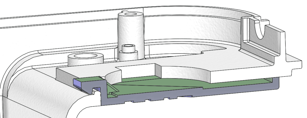
The springboard distance is the amount of opening in the mating housing that allows the door to flex. This allows the user to press down on the tip of the door to bend the door enough to release the snap fit.
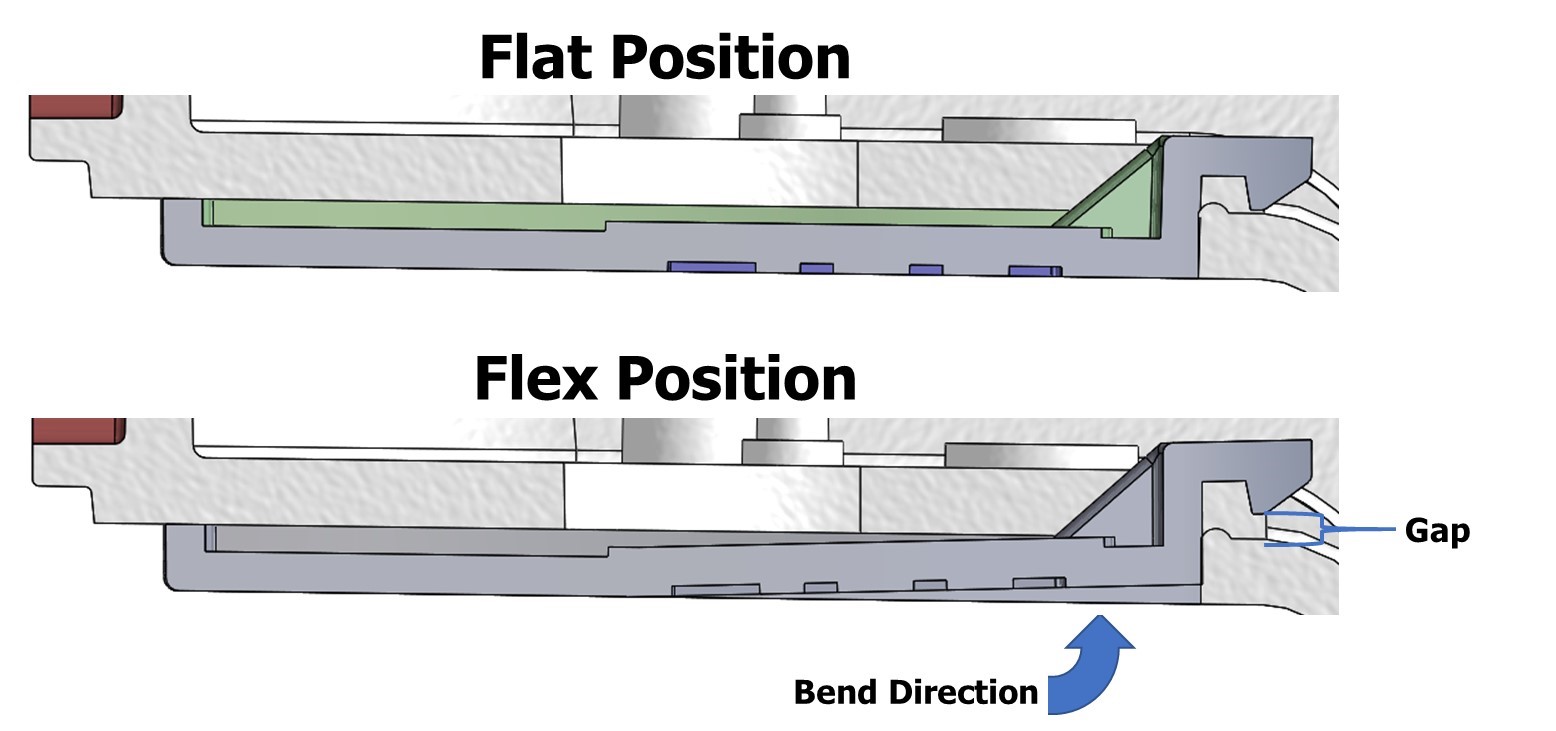
We started with a minimal interference at 0.015” and modified the springboard distance of the mating housing from very low to very high. During testing, at too large of a distance, the snap fit engagement could not be retained. At too short of a distance, the force required to disengage was well beyond what a user could exert. At the optimal distance, the door was easier to remove. However, the force a user needed was still too large, so additional design changes were required.
2. Change the Snap Feature Shape
The snap feature on the mating housing started as a rectangular shape. This created a line-to-line contact over the full length of the snap engagement. A long engagement surface contributed to the excessive force required to disengage the snap fit.
We redesigned the snap feature’s shape to be a spherical bump. Converting the line contact to point contact reduced the contact area, which decreased the force required to disengage. Optimizing the engagement would require one additional design decision.
3. Increase the Angle of Attack
With the redesigned shape of the snap feature, we needed to identify the optimal angle of attack with the area of engagement on the spherical surface. The angle of attack describes the angle of engagement between the snap feature and the sphere. Increasing the sphere increases the angle of attack. Increasing the angle of attack increases the engagement and gives a tactile and audible snap. Too low of an angle of attack provides too weak of an engagement.
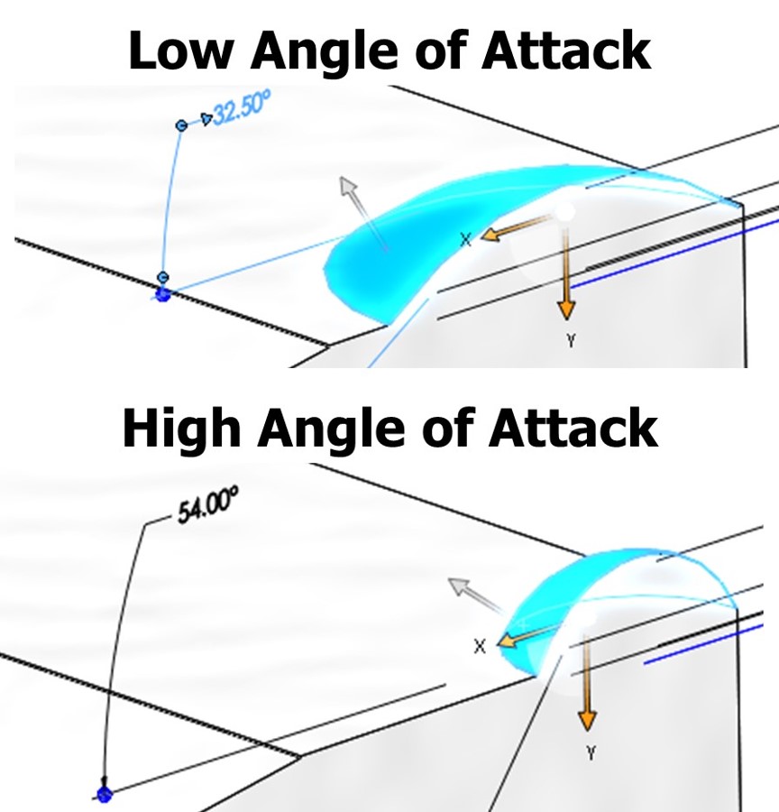
We designed and prototyped angles of attack from 32.5 to 54 degrees. The more aggressive angle was more favorable. This passed the usability test. However, then the prototype failed the drop test.
4. Increase the interference
The interference needed to be increased enough to pass the drop test without going too far and failing the usability test. We modified the geometry of the snap feature from a sphere to a rice grain. The rice grain shape increased the contact surface while maintaining the interference that worked best for users.
This final iteration maintained the usability while passing the drop test. This solution preserved the client’s budget, satisfied user requirements, and passed the drop test.
Adjusting the interference, although common, is not the only way to optimize a snap fit. At times, the interference may not even be the underlying issue. When developing snap fits for your application, remember to review the factors that influence both the fit and the feel.