Streamlining Your Assembly Process with Tolerance Stack Analysis
“Can you just make it work?”
Customers often approach us with designs that they believe are production-ready, only to find out that critical steps were overlooked, resulting in unforeseen issues during production. In many cases, customers only test a small quantity of parts that appear to be within tolerances, giving them a false sense of confidence. This is where tolerance stack analysis becomes crucial.
By analyzing the combined effect of multiple component tolerances on the final assembly, we can identify potential issues before they occur and make necessary adjustments to ensure a successful production run.
Design for Assembly (DFA) is an important process that ensures the efficient assembly of components in a product. Tolerance stack analysis is a crucial step in DFA, which involves analyzing the tolerances of individual parts in an assembly to ensure they fit together correctly.
So, instead of asking us to “just make it work,” it’s important to take the time to perform a thorough tolerance stack analysis to ensure a smooth and efficient production process.
What is Tolerance Stack Analysis?
Tolerance Stack Analysis is a method used in engineering design to evaluate the effects of dimensional variation on the performance of assemblies. It involves identifying the sources of variation in the assembly process and determining the cumulative effect on the final product.
When tolerance stack analysis is skipped, it can result in expensive errors during high-volume production.
Tolerance stack analysis is particularly important when there are separate teams responsible for designing and manufacturing a product. The analysis involves reviewing the tolerances of each individual part and considering how they will fit together in the final assembly. If the tolerances of the individual parts are not considered together, they may not fit together correctly, resulting in an assembly that doesn’t work.
Tolerance stack analysis can be illustrated using the example of a series of floorboards with a tolerance of +/- 0.005″ in width. If 200 of these boards are laid side by side, each at the bottom end of the allowable tolerance, they can create a 1″ gap on the floor, which may not be acceptable even though each board in isolation was acceptable.
Achieving specific tolerances on a part depends on two key factors:
- Process variation
- The tolerances that can be achieved in the mold
While you may not need to fully understand the underlying factors, it’s important to know when and why each step needs to be done. It’s essential to analyze and review the tolerances at each extreme, not just at individual components, but also in the overall assembly. Based on the results, update the requirements to reflect the allowable tolerances. To illustrate, consider this example.
Application
The client: A client with a diagnostics application recruited the Natech team to support their transfer from design to manufacture of their program.
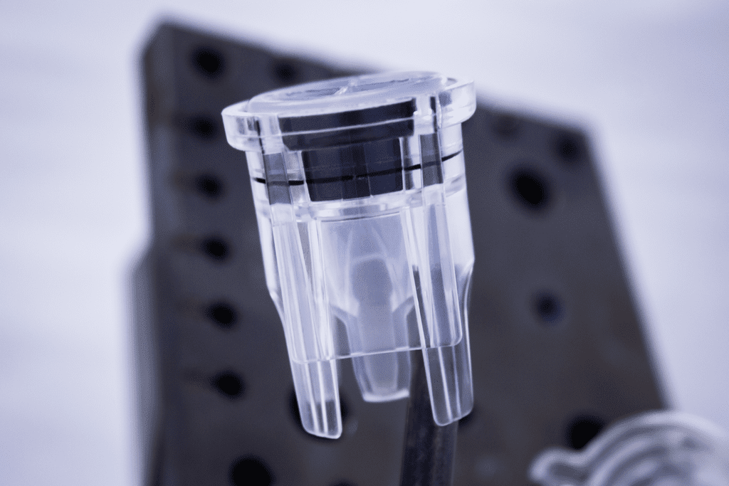
The product: The application consisting of five mating components was designed to collect a physical sample to mix with a wet reagent and a dry reagent in preparation for an optical read. The component required a vapor seal with the mating components.
Problem
However, four of the five component designs had already been defined in relative isolation, with standard tolerances defined as the part requirements. The molds were being built, and the true dimensions were still unknown.
The risk of leakage would be high if the mating features lay at the extremes of the tolerances. This risk might not be caught during development, but over time, during production, the risk would increase, causing failures in the field. In the worst-case scenario, the company would face a recall with damage to brand reputation.
Solution
Tolerance Stack Analysis
To mitigate the risk of leakage, our engineers defined the dimensional specifications to specific nominals and tolerances with an eye toward steel-safe changes. This meant that steel would be removed in the mold to achieve the desired dimension.
The engineers identified all mating components and the critical fits, labeling each critical fit A, B, C, etc. They identified the mating components and the positions they assume when interacting, which are called fitment positions. Within each fitment position, they identified all mating dimensions and assigned each mating dimension fit type as either clearance or interference.
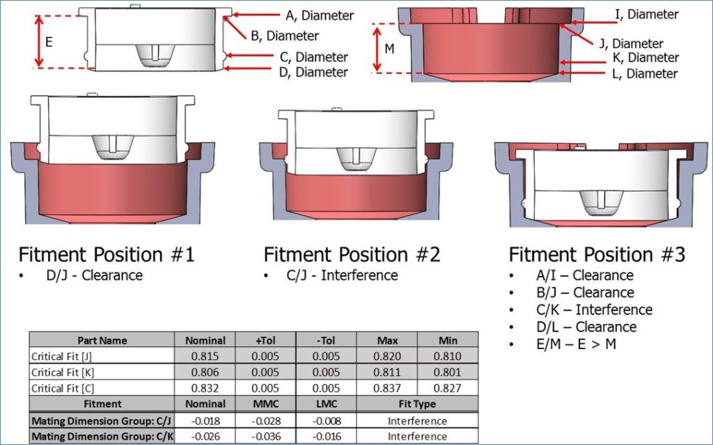
For each critical fit dimension, they listed the nominal dimension, upper and lower tolerance, and minimum and maximum allowable values. For each mating dimension group, they calculated the amount of interference or clearance for the nominal dimensions, the maximum material condition, and the minimum material condition.
Once the current state was understood, they modeled adjustments to the nominal dimensions and tolerances to optimize the fits. Each change impacted other fits, so seeing how each change influenced the overall assembly was critical. In this case, they decreased the nominal dimension of one part by 0.002″. The tolerances were also adjusted. Rather than having a nominal directly in the middle of the upper and lower tolerances, the upper tolerance became +0.000″ and the lower tolerance remained at -0.005″. This specification communicates to anyone looking at the drawing that the dimension is preferably at the top of the specification but absolutely cannot go over. The mold maker knows to start smaller on this feature and increase as needed, which is a steel-safe change. This achieved the needed fit with a nominal clearance of 0.010″.
Results
Tolerance stack analysis is crucial in reducing costs and avoiding expensive fixes during high-volume production. By ensuring appropriate tolerances are selected, unnecessary corrective actions, expensive molds, and higher piece prices can be avoided. It is essential to note that tight tolerances can slow down projects and increase costs. Therefore, it is essential to have experienced professionals perform tolerance stack analysis to achieve optimal fits while avoiding unnecessary costs.
In summary, tolerance stack analysis is a critical step in the manufacturing process that should never be skipped. It is a specific skill requiring experience that can result in fewer changes after first samples. Skipping this process can lead to expensive fixes during high-volume assembly, which is slower and riskier than performing the analysis in advance. Therefore, it is important to ensure that the tolerances selected are appropriate for the application.
The bottom line is that tolerance stack analysis is a crucial step in the manufacturing process that should never be skipped. If skipped, the issue may not be caught until high-volume assembly, leading to an expensive fix. It is important to ensure that the tolerances selected are appropriate for the application.