Avoid 3 Engineering Drawing Mistakes with GD&T
Ensure Design Success by Mastering GD&T Principles
As a designer specializing in plastic components, crafting precise engineering drawings is paramount for the long-term success of your projects. Over my extensive experience as a CMM metrologist and college professor, I’ve encountered numerous engineering drawings that unintentionally muddle communication and needlessly complicate project requirements. This unfortunate scenario arises due to a gap between functional intent and design specifications in the drawings.
Your team, spanning R&D to manufacturing, depends on well-crafted engineering drawings to effectively grasp design intent, enabling them to execute their roles seamlessly. Regrettably, flawed engineering drawings often lead to misinterpretations that result in manufacturing discrepancies and unwarranted rejection of functional parts. While some costs are apparent, others remain hidden and can persist for years.
Geometric Dimensioning and Tolerancing (GD&T) provides a standardized language for conveying design intent, following the guidelines set by ASME-Y 14.5. GD&T employs 14 geometric characteristics that emphasize crucial feature requirements in terms of Size, Form, Location, and Orientation. These GD&T symbols focus on essential feature characteristics in engineering drawings, replacing simpler yet less informative coordinates. Explore our GD&T webinar or access the webinar slides for an in-depth understanding.
To address these challenges, I’ve guided numerous clients in embracing GD&T methodologies. One of the primary steps is helping them recognize prevalent mistakes within their engineering drawings, empowering them to rectify and prevent these issues. The top three mistakes I’ve consistently observed include excessive dimensioning, incomplete specifications, and overly restrictive tolerances.
1. Over-dimensioned Engineering Drawings
Engineering drawings flooded with dimensions lose sight of the actual intent. Each part may have countless dimensions, but only a few significantly influence functionality. Focusing your engineering drawings on these critical dimensions is pivotal.
Excessive dimensioning introduces confusion by diverting attention to non-essential features. The image below illustrates how crucial dimensions can get lost amidst excessive information.
Start by clarifying functional needs. Once you’ve chosen control and functional features, establish tolerance levels. Determine the acceptable variation for your part, often involving reference points called datums.
2. Incomplete Specifications in Engineering Drawings
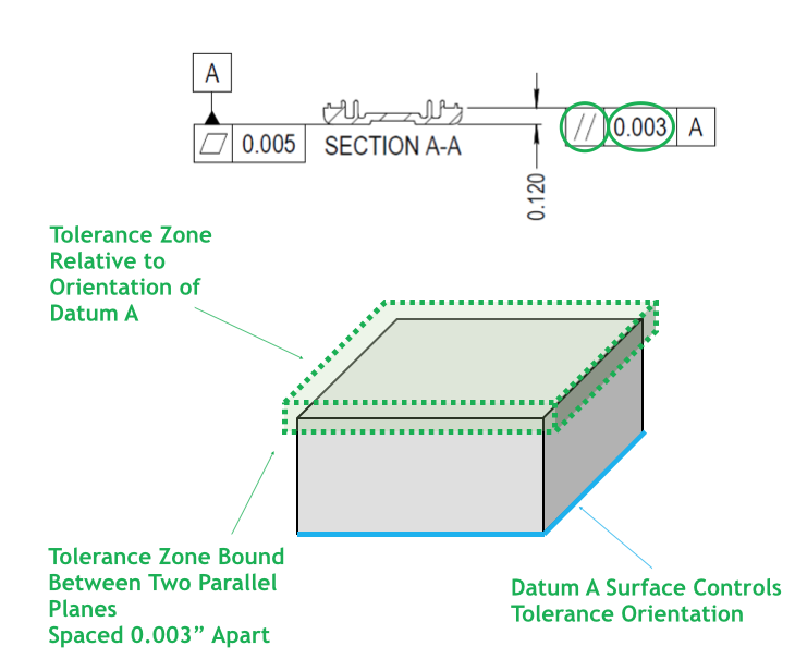
Coordinate dimensioning, a common shortcut, falls short in emphasizing form and orientation control, leading to incomplete feature specifications. This deficiency might force quality inspectors to reject functional parts needlessly.
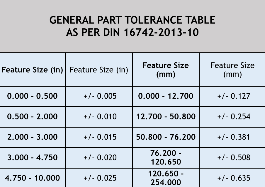
While design shortcuts might seem time-efficient, they often introduce new challenges. For instance, employing generic tolerances in engineering drawings leads to avoidable failures. A one-size-fits-all approach to tolerances doesn’t hold up; this problem magnifies in tolerance stackups.
3. Over-constrained Tolerances in Engineering Drawings
Overly tight tolerances burden manufacturing and inspection processes, escalating costs. Engineers sometimes unknowingly tighten tolerances due to a lack of understanding of critical factors.
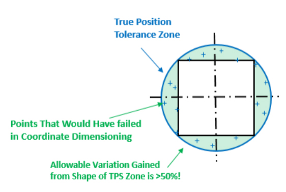
Address this limitation by implementing location control through true position, which defines a diametric tolerance zone around a feature. This approach eliminates confinement to a square tolerance zone, which might not align with a round feature’s requirements.
GD&T’s true position introduces a diametric tolerance zone that can accommodate nearly 50% more variation in hole positions compared to coordinate dimensioning. This enhanced flexibility empowers manufacturers and quality personnel, ensuring components fit seamlessly.
In your engineering drawings, true position extends its benefits to patterned holes or bosses, constraining the entire pattern within a consistent margin of allowable variation.
Conclusion: Integrating Precision with Functionality
Well-crafted engineering drawings must translate functional needs into design intent. GD&T serves as a unifying force between engineering drawings and product function. It offers a clear depiction of how parts integrate within an assembly, allowing functional simulations through measurements. By emphasizing geometric feature control over mere coordinates, GD&T conveys design intent more effectively.
Having aided numerous clients in mastering GD&T application, evaluation, and metrology, I’ve witnessed enhanced confidence in achieving repeatability and reproducibility in engineering drawings. I’m here to guide you through the journey of validating your requirements, enhancing your quality, and instilling significance into your part drawings. By sidestepping the pitfalls of excessive dimensioning, incomplete specifications, and overly constrained tolerances, you can elevate your design process.
Authored by Joe Valenti, Quality Engineer
For expert guidance in sidestepping design errors and implementing GD&T in your engineering drawings, contact me at (631) 285-2424 or via email at jvalenti@natechplastics.com.