Achieving Part Flatness through Design for Manufacturing (DFM)
When I show clients some of the parts we manufacture, I will often get asked how we achieved such precise levels of flatness on our parts. My first response always begins with the DFM analysis performed prior to the Mold Design phase of the project.
In the Design for Manufacture (DFM) phase any true decision will require tradeoffs. Sometimes being able to draw upon a wealth of experience allows engineers to intuitively focus on where to balance the tradeoffs and efficiently achieve a more optimized solution for clients. One of the major victories a thorough DFM analysis can achieve is the reduction of features. This can reduce both part complexity and material usage.
The Application
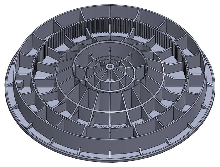
In this case, our client had added ribbing features to a part in order to ensure the necessary strength and flatness properties would be achieved once they received molded parts in hand. As part of the technical requirements, the part also included gear teeth around the entire inside diameter of one of the circular walls.

The Problem
This client had been accustomed to the iterative rapid prototyping approach to development with very limited use of analysis in advance. Uncertain about exactly how much ribbing would be necessary, the client erred on the side of caution – or so they believed.
A DFM analysis of this design revealed that it posed major potential ejection problems. As the part would cool on the core, or B-Side, of the mold, the many deep features of the part would cling to the mold, so overall ejection could be difficult and require costly mold changes. During the ejection of the part, some features would likely cling a bit more than others causing the part to get caught on the core when they should release. This would deform the part and put the flatness requirements at high risk.
The Improvement
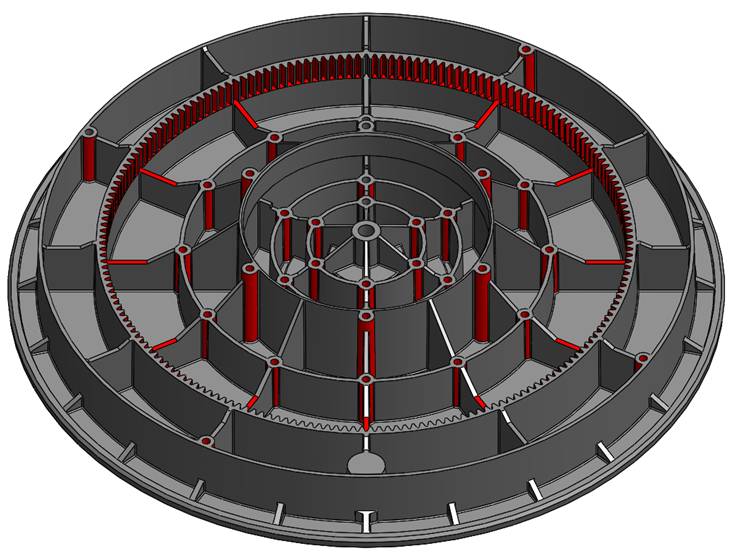
The first step was to reduce the number of ribbing features. After analyzing the wall thicknesses, feature geometries, and material, the Natech engineers suggested removal of 66 rib features. This reduced the amount of material used in the part, which reduced cost as well as part weight – all impactful victories for the client. This also improved the risk of the part not properly ejecting from the mold. This was accomplished without sacrificing the strength requirements.

The next change focused on the teeth features along the inner diameter. The actual engagement with the mating gear only extended about halfway down the height of the wall. This meant that half of the area of the teeth was not necessary. Removing these simplified the mold construction and reduced the ejection and removal risk.
Finally, to ensure a balanced, consistent ejection of the part from the machine, ejection surfaces were added to many of the rib intersection points. This adjustment dispersed the surface area of ejection enough to provide an even ejection of the part from the mold. As a result, the part experienced no hang-ups in ejecting from the mold.
The Solution
In some instances, clients are deeply committed to their approach and highly resistant to changing their process or design. We were fortunate that this client was very open to making improvements both to the part as well as to their approach to product development. Our engineers’ analytical approach was accepted as were our recommended changes to the design.
