Nov 11, 2022
What to Ask Their Quality Team Before Committing to a…
When designing products to address customer problems, the effectiveness of your engineering, development, and manufacturing teams hinges on the clarity of your designs. To ensure seamless communication of design intent and prevent long-term quality issues, it’s imperative to implement Geometric Dimensioning and Tolerancing (GD&T) in your part drawings.
The initial step in incorporating GD&T involves pinpointing the functional features crucial for optimal device performance. Amidst the numerous dimensional callouts that may populate a part drawing, only a select few significantly impact the intended function. Consider elements like mating bosses and holes on the top and bottom halves of a molded cassette – these interfacing assembly features have a direct influence on the part’s functionality.
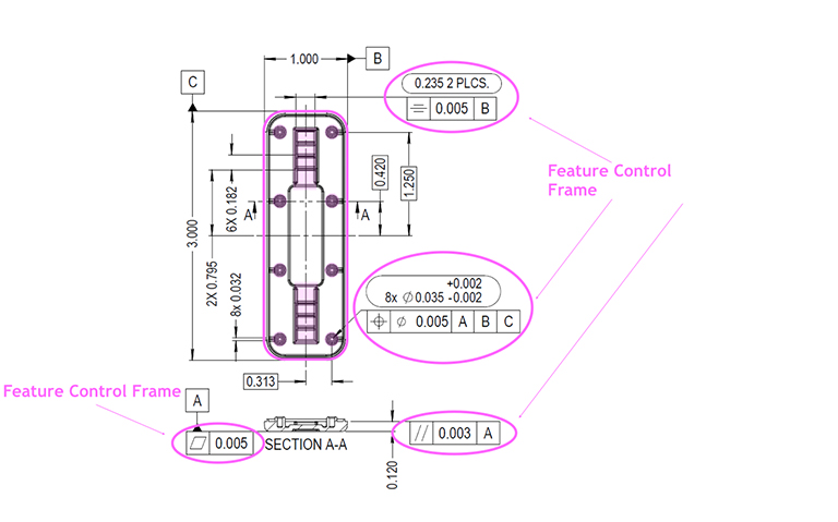
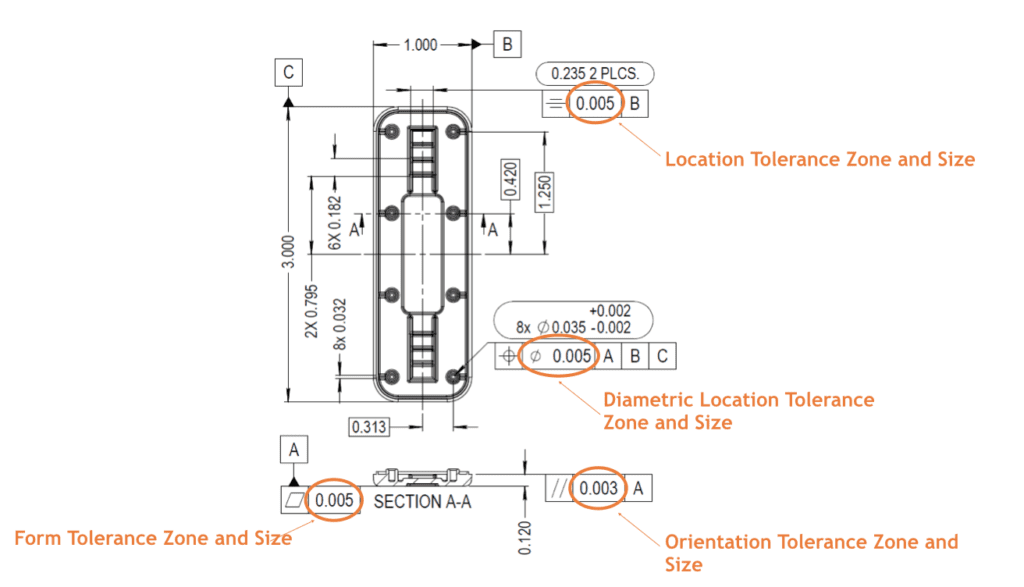
Following the guidelines of ASME-Y 14.5, there exist 14 distinct symbols for controlling form, orientation, size, or location. It’s vital to choose the control symbol that best aligns with the functional intent. Strive to avoid selecting controls that overly complicate the validation of functionality, as this could impede the evaluation process.

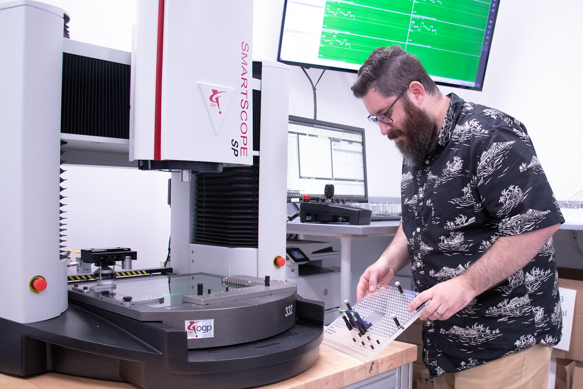
Natech’s Quality Engineer, Joe Valenti, shares his knowledge in this 30-minute webinar. Watch the Top 3 Mistakes in Engineering Drawings to learn firsthand how to avoid these critical mistakes.
Defining permissible deviation from nominal measurements is a key aspect of GD&T. Familiarize yourself with the upper and lower specification limits of your product. Rather than settling for general tolerances or overly constrained values, take the extra step during development to explore how good or bad a part can be while still functioning optimally. This approach ensures higher quality over the long term.
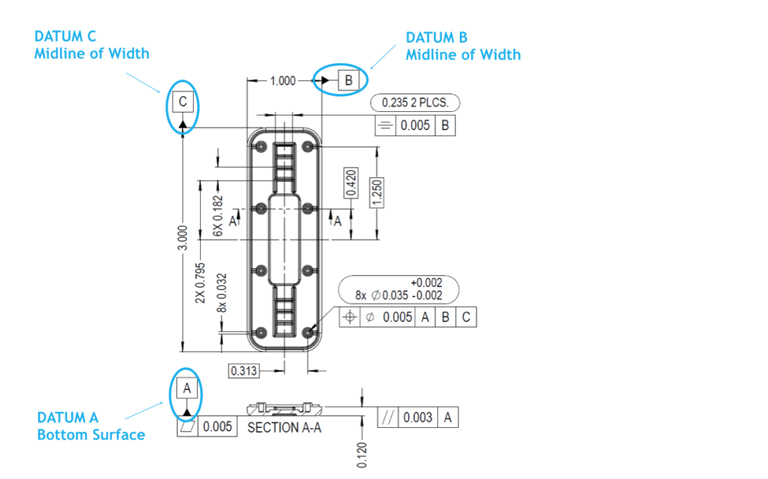
To establish external feature references, designate a Datum feature. Depending on the GD&T control characteristic, the inclusion of a Datum might be necessary for evaluation. Certain controls, such as form control, might not require Datum references, while others, like orientation and location, often rely on Datum references for accurate evaluation.
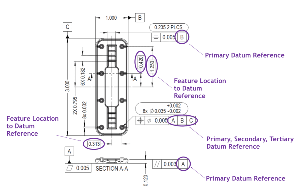
The presence of one or more Datum references at the end of a feature control frame signifies the critical features relevant to evaluating the chosen control characteristic. When fully constrained, a Datum reference frame comprises three Datum features, collectively forming a theoretical intersection. This intersection establishes both an origin point and an alignment axis, effectively restricting all six degrees of freedom around a part.
Incorporating Datum features not only ensures consistent inspection results but also promotes reproducible manufacturing quality and the ability to simulate part assemblies without physical assembly. By seamlessly implementing these five steps to introduce GD&T into your drawings, you’ll achieve design clarity that significantly enhances the long-term quality of your applications.
Article by Joe Valenti
Joe Valenti, Quality Engineer
For additional assistance in navigating GD&T application and effectively conveying functional meanings within your part drawings, connect with Joe, who has a proven track record in enhancing GD&T skills. Contact Joe at (631) 285-2424 or via email at jvalenti@natechplastics.com.