Tissue Culture Well Plate – Design for Injection Molding
Finding unique solutions to ensure part functionality and moldability for in-vitro tissue culture models
Finding the balance between achieving part aesthetics, functionality, and moldability is essential to manufacturing and producing custom diagnostic products.
The Application
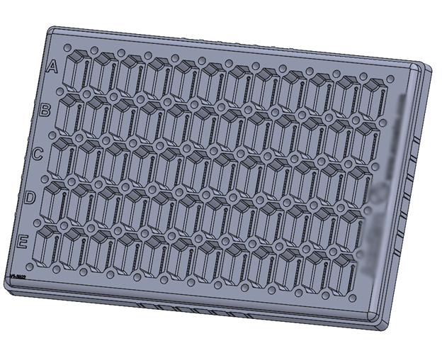
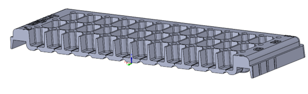
Recently, a medical company specializing in the development and growth of human tissue came to Natech with a 60 Well Plate design. The plate is used in in-vitro tissue culture models to increase drug development speed in neurotoxicity.
Essentially, the well plate is used in lab settings to hold cells and receive liquid that assists in growth of forming longer tissue chains. After tissues form and are treated with medications, researchers observe the tissue reactions and improvements. This test approach advances medical research in neurotoxicity.
The customer required a fully functional injection molded piece that worked for their application. The customer asked us to perform Design for Injection Molding (DFIM) for a part design so it could be injection molded and meet their functional and aesthetic requirements.
The analysis tools in their application require the product to be clear and transparent through both visible and infrared wavelengths. The plastic material, cyclic olefin copolymers (COC), was recommended because of its strong optical and mechanical properties.
Another critical requirement due to the application’s instruments was well spacing in both x and y directions. This meant that our engineering team had to find a way to maintain the spacing, while also derisking the design for injection molding. There was risk because the tight spacing between each well would need thin walls of metal to form these tight areas. After repeated use, these metal thin walls could be prone to breaking.
It was essential to find a manufacturing partner that could both optimize the design and injection mold the part.
Overcoming Design Challenges in the 60 Well Plate for Manufacturability
Challenge 1 – Wall Thicknesses
The customer came to us with an initial CAD design. First, the original drawing model had features that were too thick to be molded in several areas. The entire back of the well plate was thick and solid. Thick sections of plastic can cause warping in the part, due to uneven cooling in the mold.

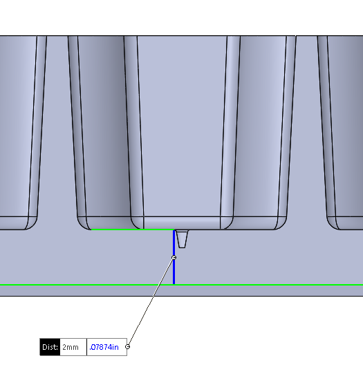
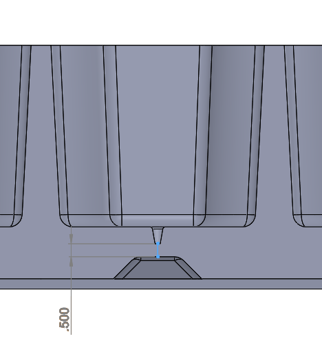
The second wall thickness concern was located at the bottom of each well. In the image on the right, the blue highlighted area is where the tissues grow. The depth of this feature is important to the application because a thin depth provided maximum transparency for the neuroscientists to view specimens under a microscope. Their goal was to have the depth measure around 0.5mm.

However, the overall thickness along the bottom was 2.0mm, which meant reducing the overall depth to only about 0.5mm was a challenge to mold because it would create choke points and limit the flow of plastic. Making this area too thin could cause freezing, short shots, uneven warping, and might not even be possible for injection molding.
Solution 1 – DFIM
We decided to create windows in the bottom of the tray to eliminate any unnecessary thick sections and address the thickness along the entire bottom of the plate. This strategy reduced potential risk in molding and optimized the part for molding.
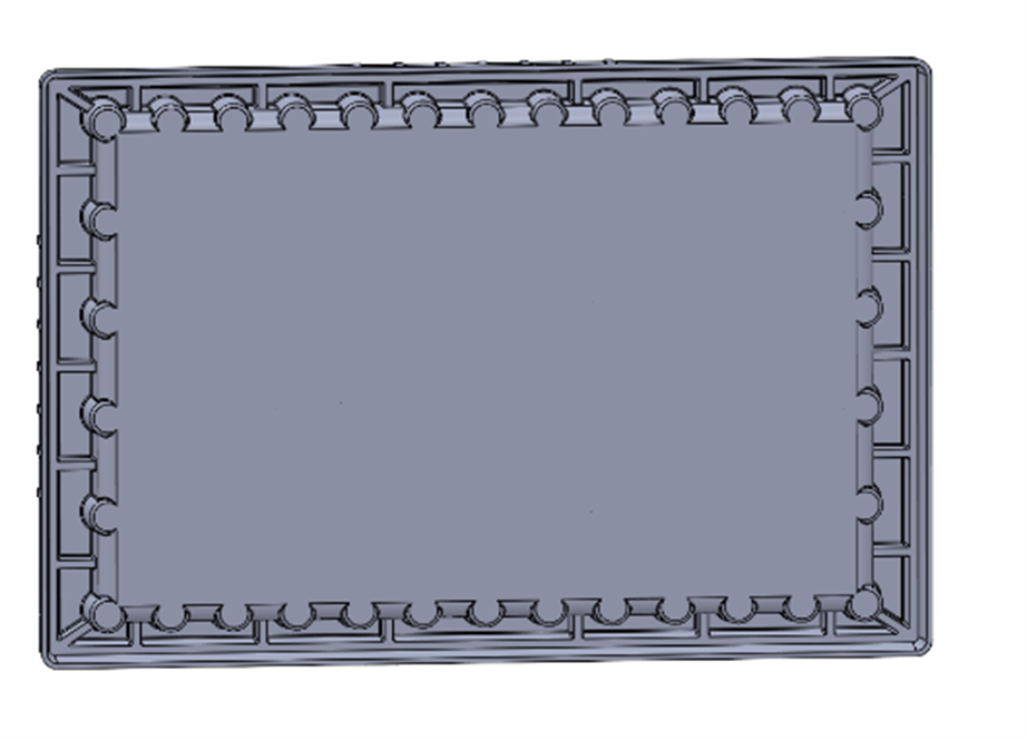

For the individual wells, we added windows directly underneath the channels to maintain the entire parent wall across the bottom at 2.0mm.
Although the thinner section was optimal for analysis, it did create choke points for plastic flow. Our solution was to create 4 different part iterations with varying depths in this area of 0.25mm, 0.5mm, 1.0mm, and 2.0mm and performed Moldflow Analysis on each of the different designs.
Moldflow allowed us to determine how thin we could make the section before there was an issue with plastic flowing. The lowest achievable thickness was 0.25mm, however, having many sections this thin posed risks during injection molding, like uneven warping, sink, and short shots. Ultimately, we determined through our analysis that a thickness of 0.50mm was the solution that was best for both the client’s requirements and moldability.
Challenge 2 – Ejection strategy
When evaluating this part, a critical area to address was determining the best way to eject the part because of the given geometry and tightly packed wells.
The walls between each well were very tight and didn’t provide enough surface area to eject on by using traditional options, such as pins or strippers. We were limited in the constraints of the size of each well and the wells’ spacing. We also needed to fit 60 wells on the part with a predetermined volume for each well.
Solution 2 – Update Geometry, Ejection Sleeves
We had to find a way to eject the part with the given circumstances. We thought out of the box and designed areas for sleeve ejection instead.
Now, the thin walls surrounding each well had an area for the part to safely eject. Consistent well volume was critical for the client, so the geometry across all wells needed to be constant. We ensured all corners of each well had a sleeve ejection cored out area resulting in consistently rounded corners for each and every well. We discussed with the customers to make sure new well volumes and geometries were acceptable.
Fillets were added for not only aesthetics but for functionality for assisting in the plastic flow throughout the mold by limiting any sharp corners and plastic hesitation. Draft was also increased to help separate the part from the B-side of the mold during ejection. A-side ejection was also included to ensure the part would not stick in the A-side either.
Achieving a Successful, Scalable Product Design with DFIM

Results 1 – Avoided Risks
Moldflow Analysis helped determine the best part design and guaranteed manufacturability. The customer was able to achieve the super thin areas where they needed it and an optically transparent part, so they could observe their results through their instrument.
However, if you keep running production, the thin sections of the mold could eventually wear down, which could cause damage such as flashing, and visual defects on the part.
We created a backup plan in these thin feature-forming areas in case they break. The backup plan was to to create a metal insert with the same well geometry of a broken area and replace it with the new metal insert. This way, the entire mold can continue to run again without getting rid of the mold.
Results 2 – Reduced Time and Costs
With the updated geometry, we were able to use ejection sleeves to eject the part from the tool. Designing for a better part in the first place avoids spending unnecessary time and thousands of dollars down the line.
If the client went to an inexperienced injection molder, they might have attempted to mold the original solid design. This would result in excessive warp, sink, and failed parts. Or the molder would reject the part and the client would ultimately need to rework their design.
Natech was able to rework their design and provide feedback to the client in order to make a fully functional injection molded part. Natech has 20+ years of experience helping bring medical and diagnostics devices from concept to commercialization. Partner with a manufacturer that knows how to deal with any challenge. Let’s bring your product to life.
Schedule Time with a Natech Engineer
Whether you need design advice or ready to kick off production, discuss your project with one of our engineers. Work with our team to create reliable and high-quality designs.