Using Design for Manufacture to Transition to Injection Molding
Application
In the dynamic world of product development, successful transitions between manufacturing methods can be both challenging and enlightening. If you’re considering a shift from machining to injection molding, our team is here to help. (Read: CNC Machining vs. Injection Molding for Product Development) At Natech, we encountered a project involving an electronic reader that exemplified the art of optimizing design for manufacture. This electronic reader consisted of 13 injection-molded parts, each playing a crucial role in its functionality.
Our task was to transition these designs from their initial state that was optimized for machining, to a form more suitable for injection molding.
Problem: Transitioning Manufacturing Process
Transitioning from machining to injection molding gave us a whole new series of challenges. The initial CAD designs were tailored for the machining process, which resulted in an intricate arrangement of components.
However, when translated into a design optimized for injection molding, the specific designs posed issues. Specifically, three main challenges emerged: addressing extra components, rethinking self-threading screw designs, and navigating the balance of thin mold steel conditions.
Solution: Simplifying the Component Design for Injection Molding
1. Addressing Extra Components
One of the initial challenges our engineers faced was the presence of extra components that had been designed with machining in mind. The feature-rich internals of one component made machining two components much easier than a single component. This was driven by the need for a bigger and bulkier material stock as well as the difficulty of machining those internal features.
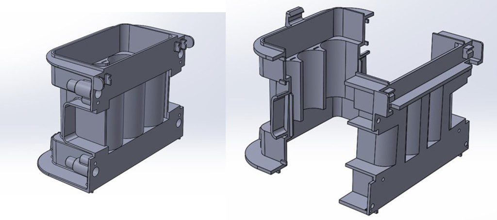
While machining processes necessitated these design choices, transitioning to injection molding created an opportunity for simplification. We delved into the intricacies of each component, assessing their functionality and examining if their fusion could streamline the overall design. By contrast, the injection molding process favored combining the two components into a single component.
The risks in the machining process no longer applied to the mass production, injection molding process. In fact, having two separate components would have increased costs, time, and risks due to the extra join and assembly step required. By removing the join, we increased the strength of the component and removed a potential leak path. This also created a huge added economic benefit of requiring one less mold for manufacture.
2. Implementing Self-Threaded Screws
The application involved self-threading screws, a feature that required meticulous handling. In the original design tailored for machining, through-holes and blind holes were utilized. These small block features or small holes served as blind bosses.
However, when translating this to injection molding, these blocks posed sink risks because of the inconsistent wall thicknesses. Using simple holes jeopardized the structural integrity under stress and torque. Our engineers took a proactive approach to devise a solutions to ensure integration of the self-threading screws.
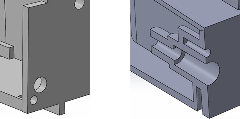
Our engineers redesigned the blind boss to maintain a consistent wall thickness, seen in the above right cross-section image. This change reduced the risk of aesthetic or functional issues on any neighboring features. The through-holes were replaced by through bosses to improve screw pull-out resistance, torque retention, vibration resistance, and hoop stress risks.
3. Utilizing Thin Mold Steel Condition
The final challenge involved the thin mold steel condition. The initial design had a narrow crevice along the bottom edge, which was a harmless feature for machining.
However, injection molding this component would require a long, thin piece of steel to form the feature. This area would be subject to high-pressure resin flow, potentially leading to deformation or breakage. Addressing this issue required a balance between maintaining functionality and bolstering mold steel robustness.
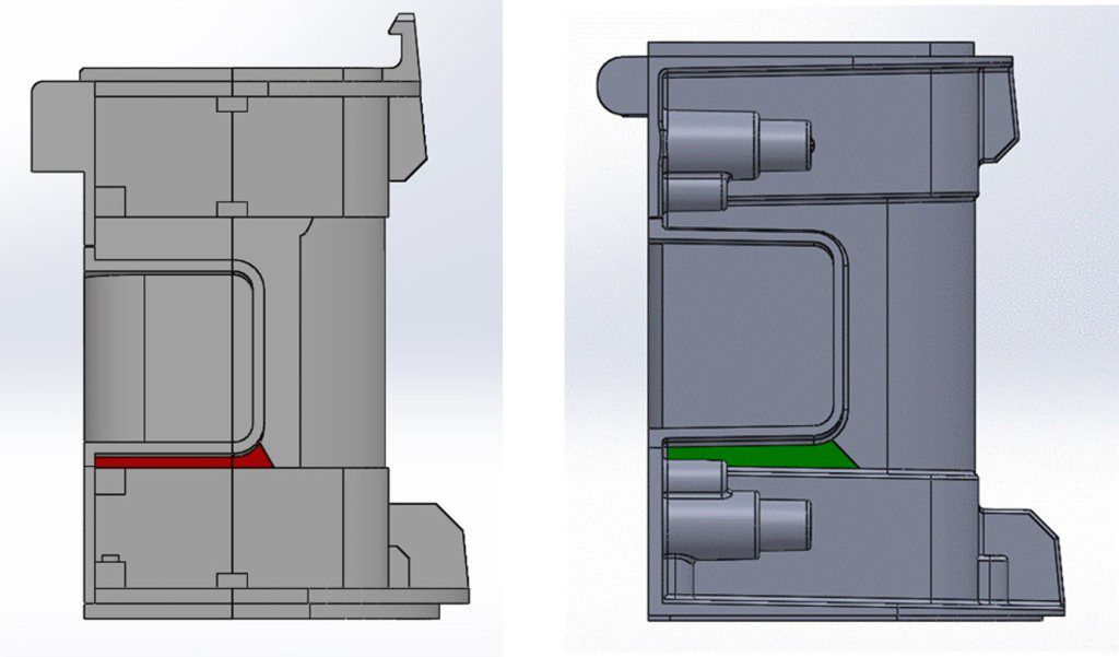
A simple adjustment of the feature and the corresponding features on the mating components allowed for a more robust steel condition. This adjustment brought a longer lasting mold with lower risk of mechanical failure.
Results: Successful Transition from Machining to Injection Molding
By optimizing the design for injection molding, we achieved multiple benefits. The streamlined components led to:
- Reduction in complexity during manufacturing 🠮 enhancing overall efficiency
- Rethinking self-threading screw designs 🠮 components that could withstand the demands of injection molding while maintaining their intended functionality
- Adjustments to thin mold steel conditions 🠮 a more robust mold design and safeguarding against potential structural issues during the molding process
This case study displays essence of design for manufacturing – achieving complexity with efficiency. Through collaborative problem-solving and a deep understanding of both machining and injection molding processes, our engineers successfully optimized the design for manufacture.
This journey emphasizes the importance of iterative design, cross-functional teamwork, and a commitment to delivering efficient and functional designs that allow a seamless transition from one manufacturing phase to another.
At Natech, our engineers continually strive to push the boundaries of design, creating solutions that optimize both form and function in the continuously evolving realm of product development.