Beginner’s Guide to Design for Injection Molding: Filling
Learn the Basics of Plastic Injection Molding: Designing for Filling Success
Table of Contents
- Homepage
- Design for Injection Molding: Filling
- Design for Injection Molding: Cooling
- Design for Injection Molding: Ejection
- Design for Injection Molding: Assembly
- Design for Injection Molding: Inspection
The design for the injection molding filling phase is a critical aspect of the overall injection molding process. This phase involves the precise delivery of melted plastic into the core and cavity of the injection mold under high temperature and pressure.
To ensure a successful fill process, here are three key considerations your engineer must carefully assess when designing for fill.
1. Gate Marks
Situation
When the molten plastic enters the core and cavity, it passes through a small opening called the gate. However, this gate leaves a visible mark on the final plastic part. The type and size of the gate vestige depend on the chosen gate design. Watch the video below to understand what gate vestige looks like and how it forms.
Solution
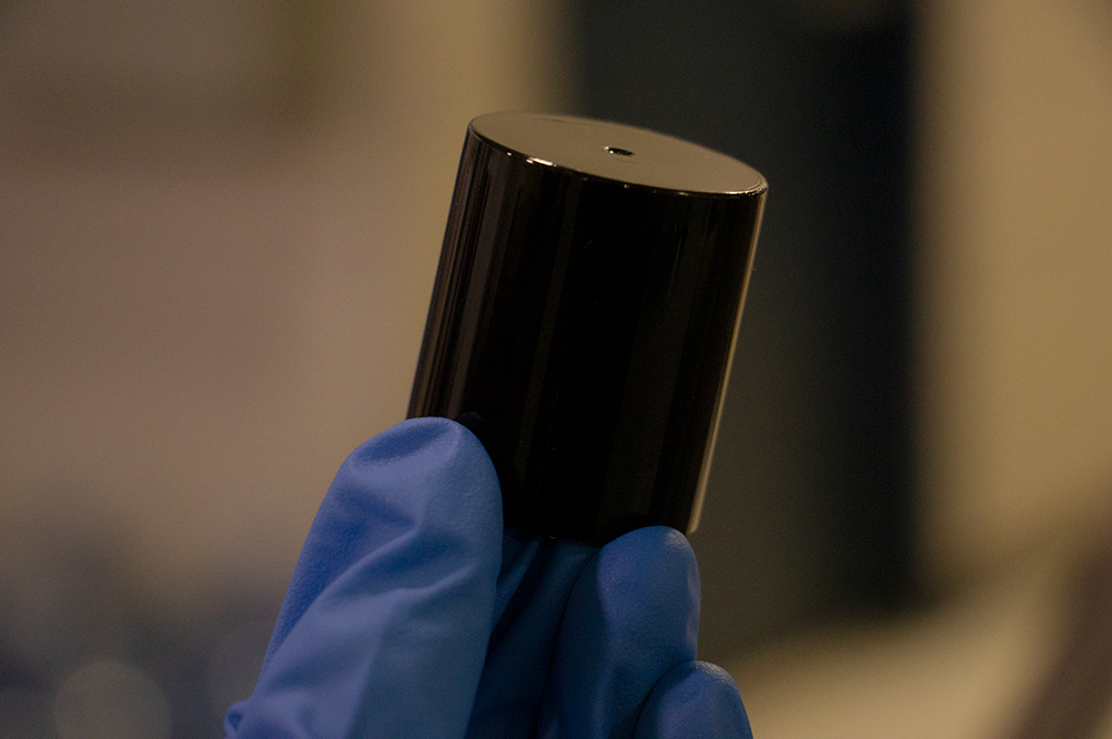
To tackle this issue, the injection molding engineer considers various factors such as gate type, gate location, and resulting gate vestige. Ideally, the engineer updates the part drawing to specify the surfaces on the part that can or cannot be used for gating, aiming for the best possible outcome. The image below shows a part with a gate mark in the center of the part. It’s important for you engineer to design your part so that vestige does not impact functional or aesthetic requirements.
2. Vent Marks
Situation
During the filling process, the core and cavity of the mold may trap air or gas, hindering the proper filling of the plastic.
Solution
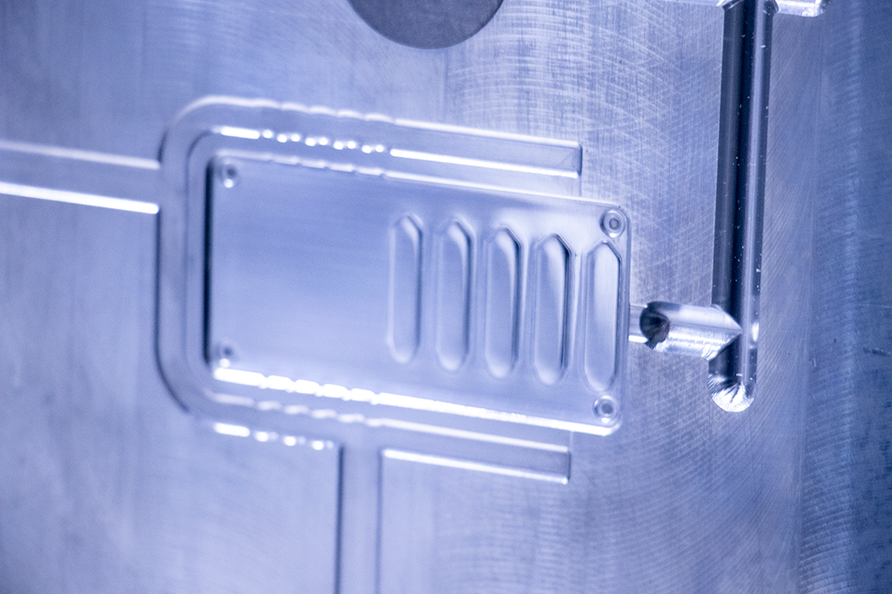
To overcome this challenge, the injection molding engineer strategically places vents in the mold. These vents allow the gas to escape while preventing the plastic from leaking through them. However, it’s important to note that these vents can leave visible marks on the final part. The engineer must strike a balance between necessary venting from an injection molding perspective and potential vent marks from an aesthetic standpoint. In the images below, the “moat” surrounding the part indicates the vent areas.
3. Addressing Thin-Steel Conditions
Situation
Certain part designs require the use of thin steel in the mold, particularly in areas with narrow gaps. However, the injection molding process subjects this thin steel to high temperatures and pressures. Over time, the steel area could be stressed by the flow of hot resin, which can lead to deformation and eventual bending or breakage.
Solution
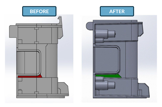
To mitigate this risk, the engineer responsible for the design for injection molding must identify potential thin-steel conditions. If they hold significant accountability, they will propose solutions that prioritize both functionality and aesthetic requirements. In the example below, a simple adjustment of feature allowed for a more robust steel condition. The adjustment brought a longer lasting mold with lower risk of mechanical failure.
Ensure Success During Manufacturing
The design for the injection molding filling phase is crucial for achieving successful outcomes. Addressing gate marks, vent marks, and thin-steel conditions ensures optimal functionality and aesthetics of the final part. By considering these factors, engineers can minimize defects, enhance efficiency, and improve your overall product quality in the injection molding process.
If you need assistance with design for manufacturing and injection molding, our team is here to help. We have the expertise and experience to optimize your designs and ensure seamless integration into the injection molding process. Contact us today to discuss your project and take advantage of our comprehensive design services.
←Previous Post ㅤㅤㅤㅤㅤㅤ Next Post→